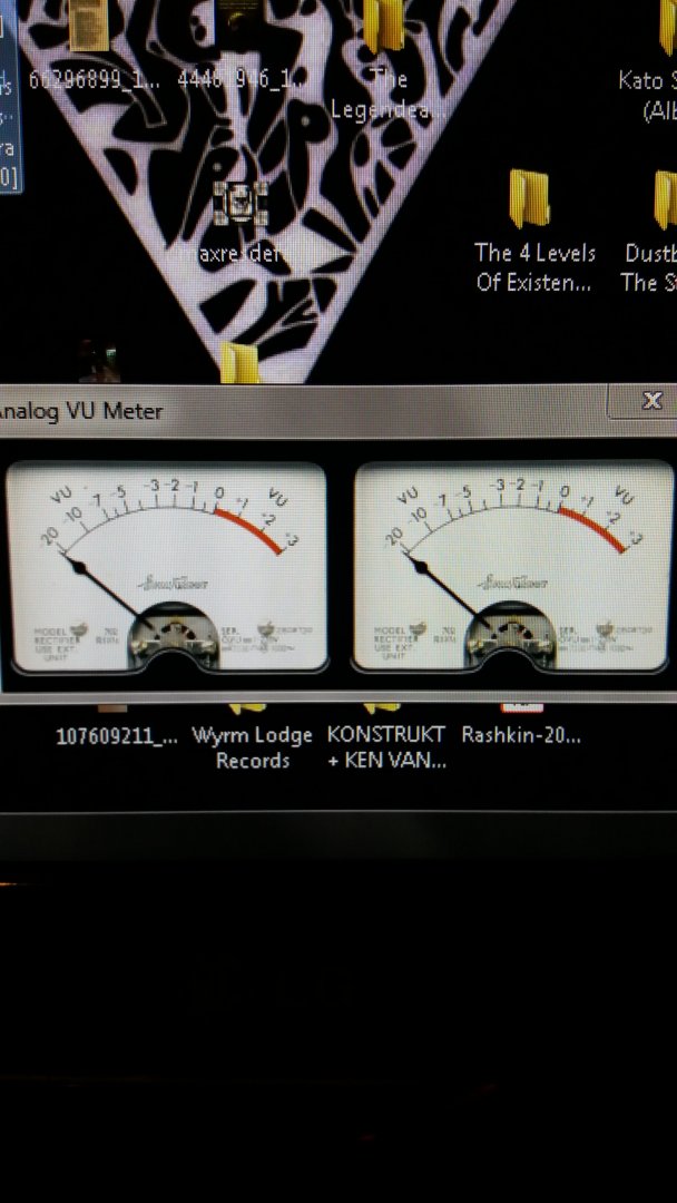
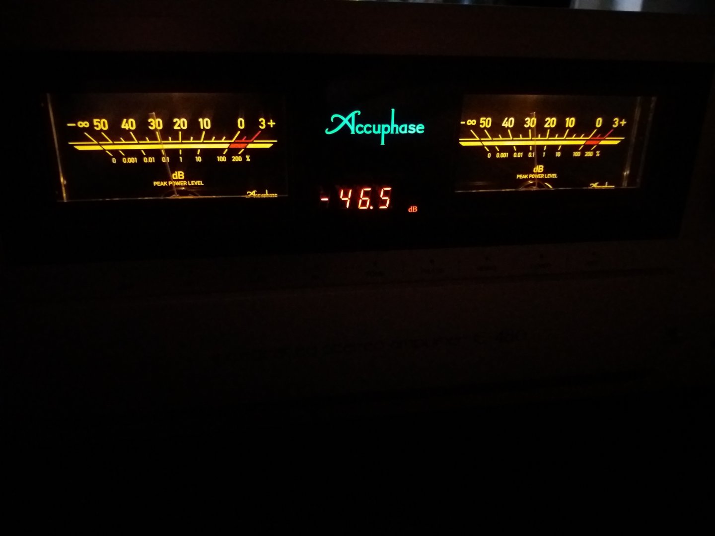
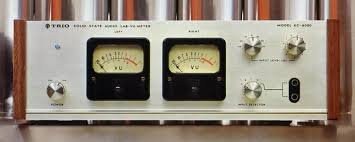
Αν και στα ηλεκτρονικα δεν τα καταφερνω ειπα να δοκιμασω να φτιαξω ενα VU meter box με αλουμινενια προσοψη και ξυλινα πλαινα για να ταιριαζει με τον ενισχυτη μου. θελω κατι που να μοιαζει καπως σε αυτο
αλλα. Βρηκα στο bay καποιες πλακετες (συγχωρεστε με για την αγνοια ορολογιας) που οδηγουν τα meters. Το ερωτημα μου ειναι, σημα απο που τους δινω?
Μπορω να βγαλω πχ απο το Rec out του ενισχυτη? Σκεφτομαι πως μαλλον οχι γιατι αυτο που βγαινει απο εκει ειναι σταθερο και δεν θα κουνιουνται οι βελονες. Μηπως απο το pre out?
Διαφορετικα μηπως απο τις εξοδους των ηχειων? Σε αυτην την περιπτωση θα στριμωξω σε καθε εξοδο ενα καλωδιο που θα πηγαινει στα ηχεια και ενα στο μηχανακι που παω να φτιαξω? Μηπω ανατιναξω τιποτα?
Σας παραθετω τις οδηγιες του κατασκευαστη και αν μπορειτε βοηθηστε!
Vers
Instructions for use: 1 signal input: driver board provides two input methods, according to your situation, choose one! (Hint: If the volume potentiometer back, or take amplifier output signal, the pointer swings will be controlled volume potentiometer, ie large volume pointer swing big, small volume is small then the pointer swings.)A: LOW, GND, LOW: This is the driver board low signal input terminals for SPIDERS CD player, computer sound cards, before the class, and other audio equipment, audio signal wiring LOW, GND, LOW respectively: left, , the right channel can be.(Driver board two potentiometers, you can adjust the size of swings hands, such as signal full open, the pointer swings failed to meet your expectations, you can drive panel R2, R3 resistor removed, R2, R3, is used to drive the board connected high input signal attenuation resistor to ground, and only in the use of high input will be used, because they were unable to determine your particular type of signal input, so finished the drive plate R2, R3, are welded, removed the resistor is much easier than welding up, after all, not everyone has the welding equipment, Oh, of course, which is a special case and, usually are not removed!)B: HIGH, GND, HIGH: This is the driver board high signal input terminals for connections are amplified through the amplifier power signal, the drive plate-site attenuation circuit amplifier output will be high-intensity level attenuation and sent to driver IC, the attenuator circuit now contains just mentioned resistors R2 and R3, connecting the output terminal of the amplifier unit, the drive plate HIGH two terminals respectively connected to the amplifier terminals of the two red, two black terminal of amplifier , choose any one driver board connected to the GND terminal. 2 drive output: V +, V-, terminal: This is the driver board for the table header backlight, backlight provides two 12V power supply output terminals, connectors, please note the matching table header source voltage, and the positive and negative direction. +, -, Terminals: This is the driver board driver header output terminals respectively connected to the two-level table "+" "-" terminals connected to the positive and negative attention. 3 Power supply parameter: Operating voltage: AC / DC 12-15V AC and DC wide range of operating voltages (recommended separate power transformers, power supply or a separate windings for!) Rated power: 3W 4 PCB Size: 60 *39mm 5 Accessories: Header connector half a meter into two use. Finished products have been energized aging test, press your chosen model header precise tuning! 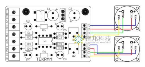
|


")